1
/
of
4
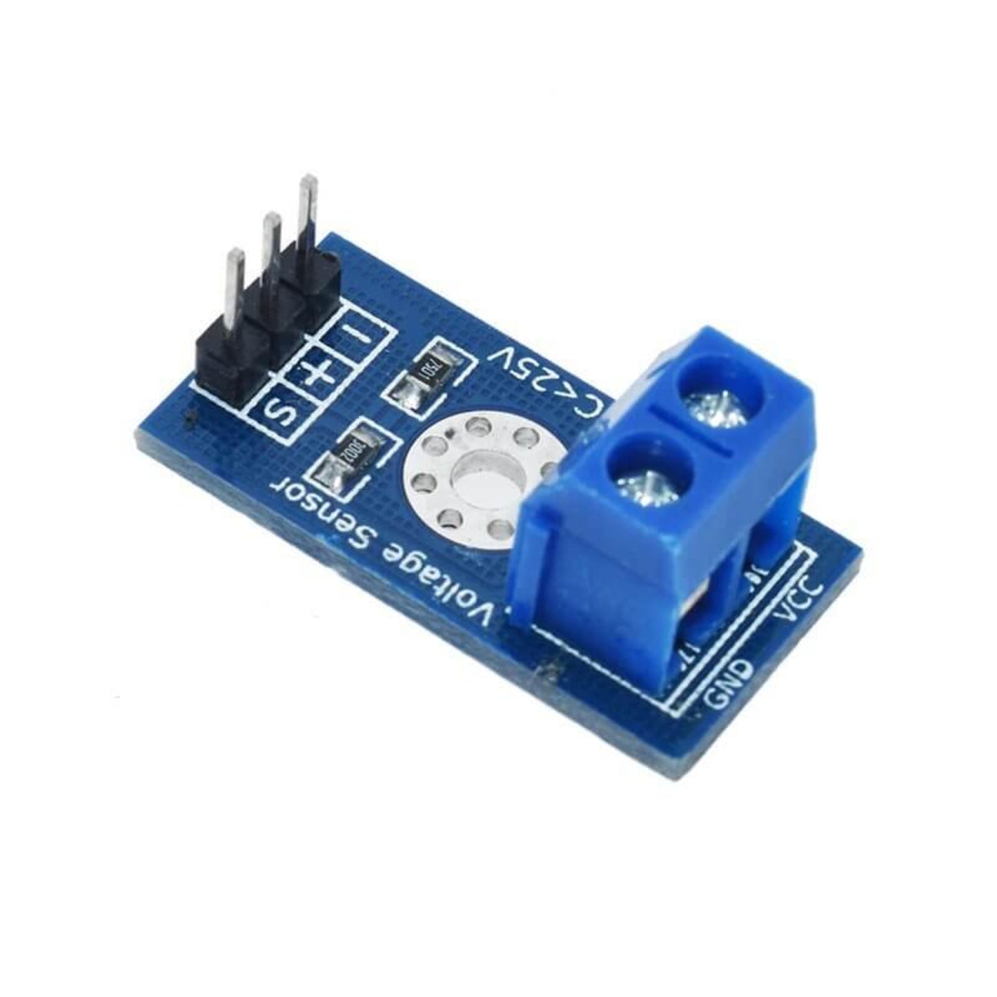
DC 0-25V Voltage Sensor Module (Resistive Divider) for Arduino
DC 0-25V Voltage Sensor Module (Resistive Divider) for Arduino
🔥 13 sold•✓ In stock
Regular price
HK$10.00
Regular price
Sale price
HK$10.00
Shipping calculated at checkout.
Quantity
Couldn't load pickup availability
Delivery Options
Delivery Options
- Local delivery within Hong Kong and in-store pickup.
- Free shipping for orders of HK$400 or above; HK$35 shipping fee for orders below HK$400.
- Shipped by SF Express, usually dispatched the same day for orders confirmed before 6:00 PM (Mon–Sat).
- Estimated delivery time: 1–3 business days after dispatch (Hong Kong).
- In-store pickup details (location and time) will be confirmed by email or phone message.
- Delivery times are estimates and may be affected by weather or unforeseen circumstances.
🔋 [DC 0-25V High-Precision Voltage Sensor Module]
This voltage detection module is designed based on the resistive divider principle, which safely scales down an input voltage of up to 25V by a factor of 5. This allows the high voltage to be safely read by the analog input pin of microcontrollers like the Arduino. It is an ideal component for battery level monitoring, power projects, and general electronic experimentation.
✨ Key Features
- Divider Design: Utilizes a resistive voltage divider circuit to reduce the input voltage by a 5:1 ratio.
- Wide Voltage Range: Supports a DC voltage input range from 0V to 25V.
- High Resolution: Analog resolution of 0.00489V (based on a 5V system).
- MCU Compatible: Works with both 5V and 3.3V microcontroller systems (check maximum input voltage limits accordingly).
📋 Technical Specifications (Parameters)
| Parameter | Value | Note |
| Voltage Input Range | DC 0V - 25V | Refer to the next point for the minimum detectable voltage. |
| Voltage Detection Range | DC 0.02445V - 25V | Minimum detectable input voltage is approximately 0.02445V. |
| Voltage Analog Resolution | 0.00489V | Based on a 5V system (5V / 1023). |
| Voltage Division Ratio | 5:1 |
🔌 Wiring Guide
| Interface | Connection | Description |
| DC Input (External Power) | Positive to VCC, Negative to GND | Connects to the DC voltage source (0-25V) you wish to measure. |
| Output Interface (MCU) | "+" to 5V/3.3V (Power) | Connects to the VCC/power supply pin of your Arduino/MCU. |
| Output Interface (MCU) | "-" to GND (Ground) | Connects to the common ground of your Arduino/MCU. |
| Output Interface (MCU) | "S" to Arduino AD Pin | Connects to an Analog Input Pin of the Arduino (e.g., A0, A1). |