1
/
of
3
L9110S Dual DC & Stepper Motor Driver Board Module for Arduino
L9110S Dual DC & Stepper Motor Driver Board Module for Arduino
🔥 13 sold•✓ In stock
Regular price
HK$15.00
Regular price
Sale price
HK$15.00
Shipping calculated at checkout.
Quantity
Couldn't load pickup availability
Delivery Options
Delivery Options
- Local delivery within Hong Kong and in-store pickup.
- Free shipping for orders of HK$400 or above; HK$35 shipping fee for orders below HK$400.
- Shipped by SF Express, usually dispatched the same day for orders confirmed before 6:00 PM (Mon–Sat).
- Estimated delivery time: 1–3 business days after dispatch (Hong Kong).
- In-store pickup details (location and time) will be confirmed by email or phone message.
- Delivery times are estimates and may be affected by weather or unforeseen circumstances.
Compact yet powerful, the L9110S Dual Channel Motor Driver Module is an essential component for your robotics and smart car projects. Designed to be a more efficient and smaller alternative to the L298N, this H-Bridge driver can simultaneously control two DC motors or one 4-wire 2-phase stepper motor. It is fully compatible with Arduino, microcontrollers, and various DIY electronic kits.
Key Features:
- Dual H-Bridge Design: Capable of driving 2 DC motors or 1 stepper motor independently.
- Wide Voltage Range: Supports motor operating voltages from 2.5V to 12V.
- Current Capacity: Handles a continuous current of 0.8A per channel, suitable for most standard smart car motors.
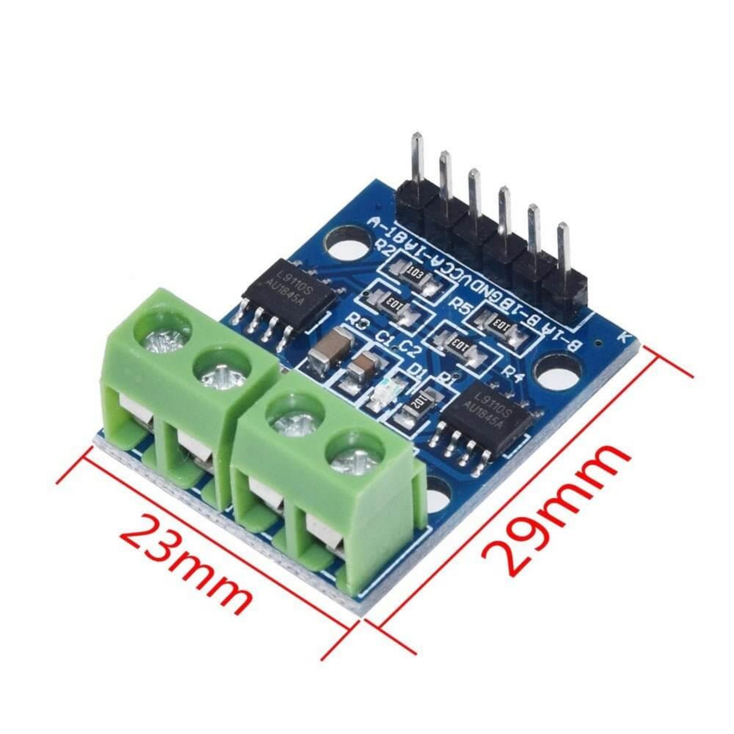
- Compact Footprint: Ultra-small PCB size (29mm x 23mm) makes it easy to fit into tight enclosures.
- Easy Installation: Equipped with 3mm mounting holes for secure attachment.
Technical Specifications:
- Chip: Dual L9110S
- Supply Voltage: DC 2.5V - 12V
- Max Operating Current: 0.8A per channel
- Dimensions: 29mm x 23mm x 12mm (approx.)
- Interface: TTL / CMOS output level compatible
Pinout & Wiring Guide:
-
6-Pin Header (Control Inputs):
- VCC: External Voltage (2.5V-12V)
- GND: External Ground
- A-1A / A-1B: Microcontroller IO ports for Motor A
- B-1A / B-1B: Microcontroller IO ports for Motor B
-
4-Pin Screw Terminal (Motor Outputs):
- Motor A: Connect to DC Motor A (No polarity)
- Motor B: Connect to DC Motor B (No polarity)
How to Use (Logic Table): Simply connect VCC and GND to power the module (Power LED will light up). Control the direction by sending High/Low signals from your microcontroller:
- Forward: Input A High, Input B Low
- Reverse: Input A Low, Input B High
- Stop/Idle: Both Inputs Low or Both Inputs High