1
/
of
3
L298N Dual H-Bridge Motor Driver Module for Arduino & Raspberry Pi
L298N Dual H-Bridge Motor Driver Module for Arduino & Raspberry Pi
🔥 11 sold•✓ In stock
Regular price
HK$20.00
Regular price
Sale price
HK$20.00
Shipping calculated at checkout.
Quantity
Couldn't load pickup availability
Delivery Options
Delivery Options
- Local delivery within Hong Kong and in-store pickup.
- Free shipping for orders of HK$400 or above; HK$35 shipping fee for orders below HK$400.
- Shipped by SF Express, usually dispatched the same day for orders confirmed before 6:00 PM (Mon–Sat).
- Estimated delivery time: 1–3 business days after dispatch (Hong Kong).
- In-store pickup details (location and time) will be confirmed by email or phone message.
- Delivery times are estimates and may be affected by weather or unforeseen circumstances.
Are you looking to control DC motors or stepper motors with your Arduino, Raspberry Pi, or Microbit?
The L298N Dual H-Bridge Motor Driver Module is your perfect solution! This versatile and robust module allows you to easily manage the speed and direction of two DC motors or one 2-phase stepper motor, making it an essential component for robotics, automation, and DIY electronics projects.
Key Features:
- Dual H-Bridge Design: Control two independent DC motors or one 2-phase 4-wire stepper motor.
-
Wide Voltage Compatibility:
- Logic Voltage: 5V
- Driver Voltage: 5V - 24V (Supports up to 46V with external 5V logic supply)
- High Current Output: Each bridge can handle a maximum continuous current of 2A (3A peak instantaneous current), with a total rated power of 25W.
- PWM Control Ready: Easily control motor speed using Pulse Width Modulation (PWM) signals through the ENA and ENB pins.
- Built-in 5V Regulator: For driver voltages between 7V-12V, the module can provide a stable 5V output to power your microcontroller (e.g., Arduino). Note: For driver voltages above 12V, an external 5V logic supply is recommended to protect the onboard regulator.
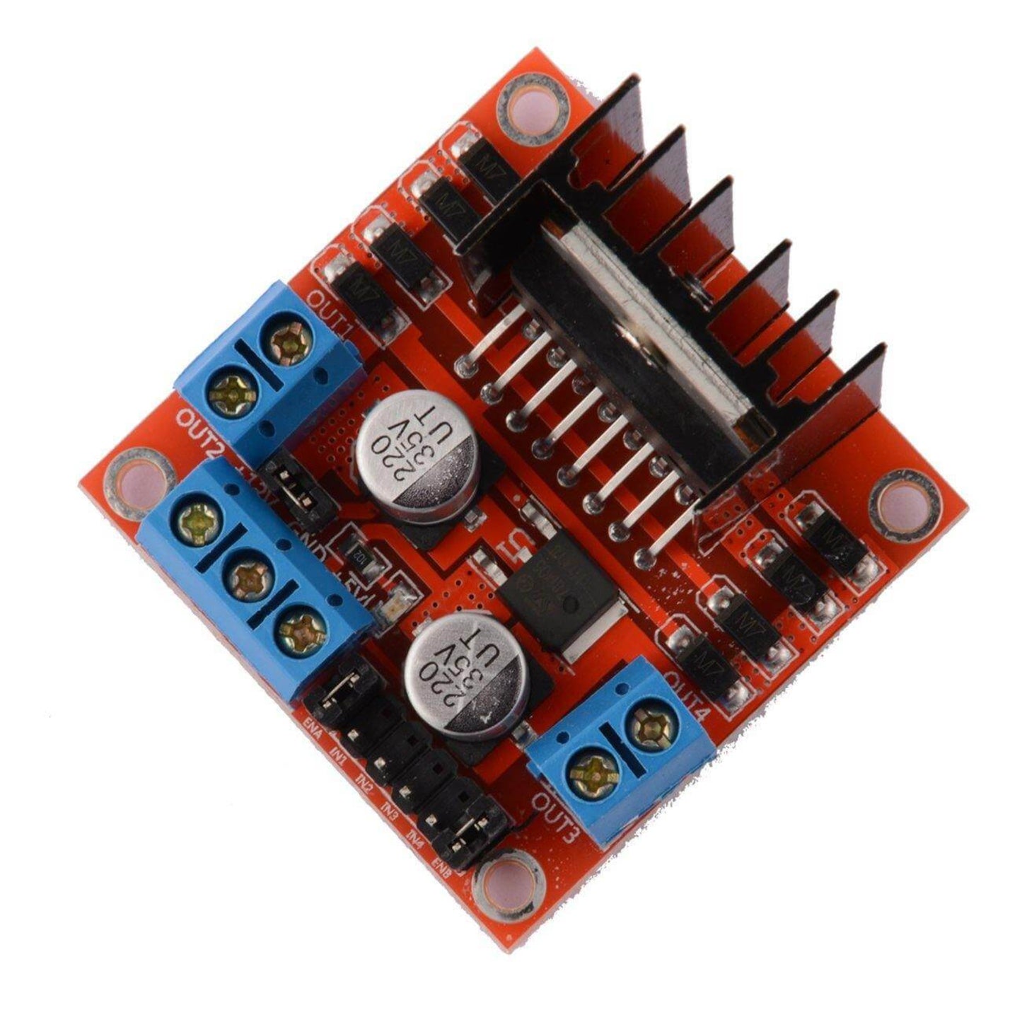
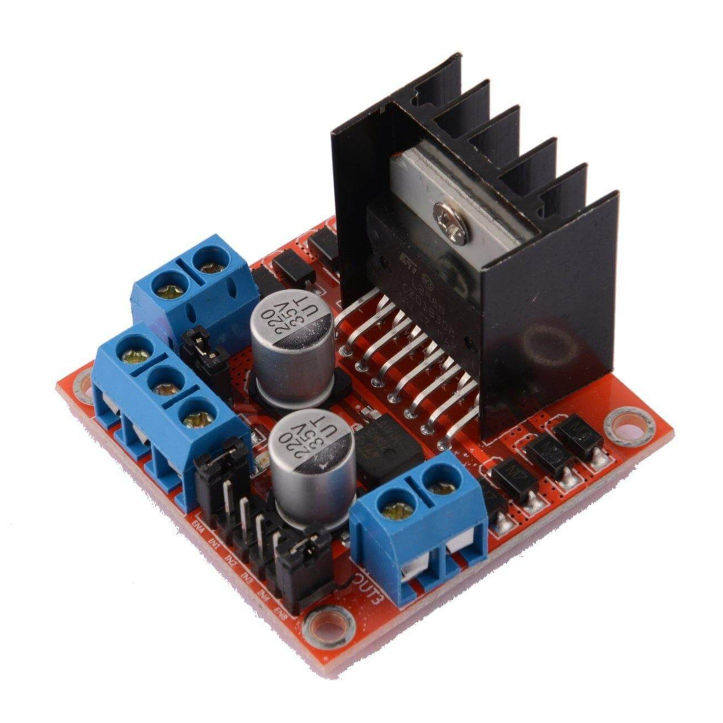
- Robust & Reliable: Features an L298N main control chip from ST company, known for strong driving ability, low heat generation, and excellent anti-interference.
- Large Capacity Filter Capacitor & Protection Diodes: Enhances reliability and protects your circuit from current spikes.
- Compact & Lightweight: Measuring 43x43x27mm and weighing only 30g, it's easy to integrate into your designs.
Applications:
The L298N motor driver is ideal for a wide range of applications, including:
- Robotics (e.g., smart obstacle avoidance cars, line-following robots)
- Controlling DC motors and stepper motors
- Driving relay coils and other inductive loads
- Educational projects with Arduino, Raspberry Pi, Microbit, and other development boards.
How it Works:
The L298N chip is a high-voltage, high-current full-bridge driver. It takes standard logic level signals for control.
- IN1 & IN2: Control Motor A (OUT1 & OUT2)
- IN3 & IN4: Control Motor B (OUT3 & OUT4)
- ENA: Enables/disables Motor A and controls its speed with PWM.
- ENB: Enables/disables Motor B and controls its speed with PWM.
Connection Guide & Important Notes:
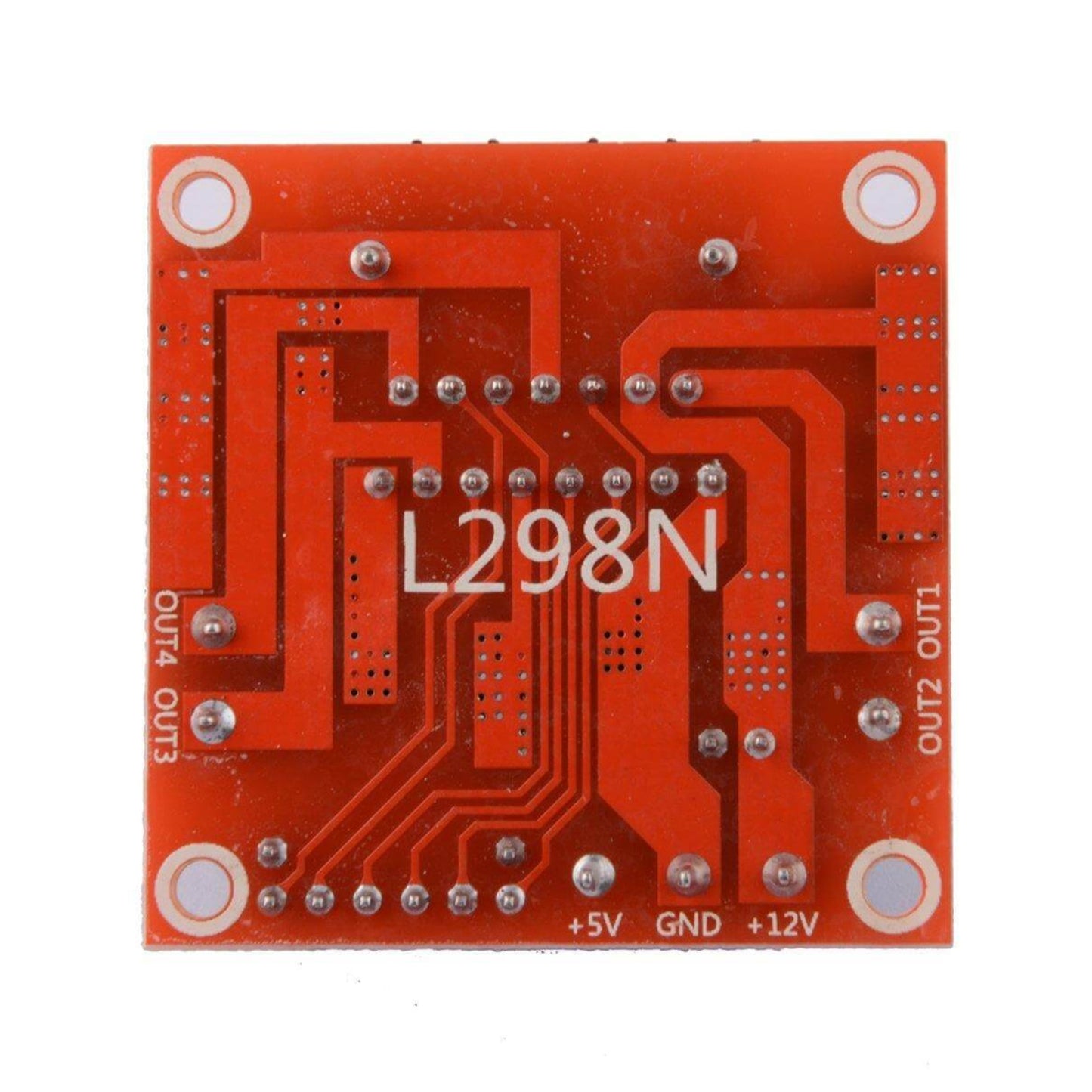
A. Power Supply Connection:
- +12V (or Driver Voltage): Connect your main power supply's positive terminal (DC 5V-24V).
- GND: Connect your main power supply's negative terminal and ensure it's common with your microcontroller's GND.
- +5V Output: This pin provides a regulated 5V output (if the onboard 5V jumper is connected and driver voltage is 7-12V). You can use this to power your Arduino or other MCU.
- Onboard 5V Jumper Cap: When connected, the onboard 5V regulator is enabled. Important: If your driver voltage is above 12V, remove this jumper and provide an external 5V supply to the +5V output pin for the L298N's logic circuit to prevent damage to the onboard regulator.
B. Motor Connection:
- Motor A: Connect to OUT1 and OUT2 terminals.
- Motor B: Connect to OUT3 and OUT4 terminals.
- If a motor spins in the wrong direction, simply swap its two connection wires.
C. Digital Signal Input (IN1, IN2, IN3, IN4):
- Connect these pins to your microcontroller's GPIO pins.
-
Motor Control:
- Forward/Reverse: Set one IN pin HIGH and the other LOW (e.g., for Motor A, set IN1 HIGH, IN2 LOW for one direction; IN1 LOW, IN2 HIGH for the other).
- Stop: Set both IN pins HIGH or both LOW (ensure your code manages this for proper stopping behavior).
D. ENA & ENB Control:
- For PWM Speed Control: Remove the jumper caps from ENA and ENB. Connect ENA and ENB to your microcontroller's PWM-capable GPIO pins.
- For Full Speed (No PWM): Leave the jumper caps on ENA and ENB. This enables both channels for continuous operation at full power based on your IN signals.