L298 2 Route Motor Driver Module - 160W 7A High Power H-Bridge
L298 2 Route Motor Driver Module - 160W 7A High Power H-Bridge
Couldn't load pickup availability
Delivery Options
Delivery Options
- Local delivery within Hong Kong and in-store pickup.
- Free shipping for orders of HK$400 or above; HK$35 shipping fee for orders below HK$400.
- Shipped by SF Express, usually dispatched the same day for orders confirmed before 6:00 PM (Mon–Sat).
- Estimated delivery time: 1–3 business days after dispatch (Hong Kong).
- In-store pickup details (location and time) will be confirmed by email or phone message.
- Delivery times are estimates and may be affected by weather or unforeseen circumstances.
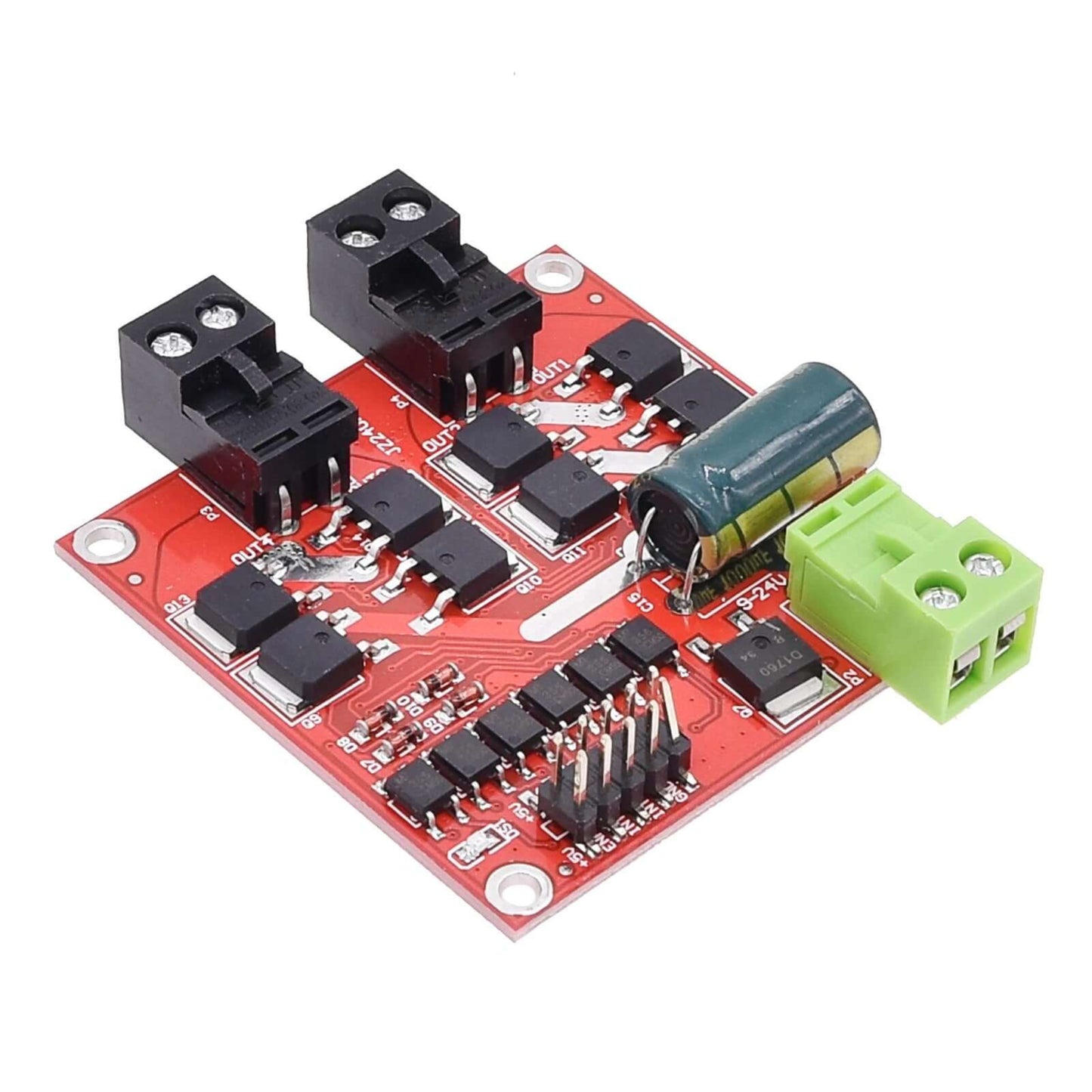
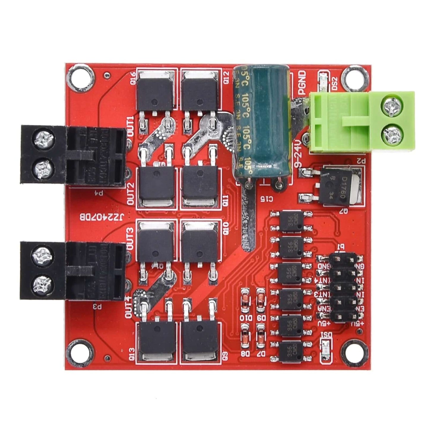
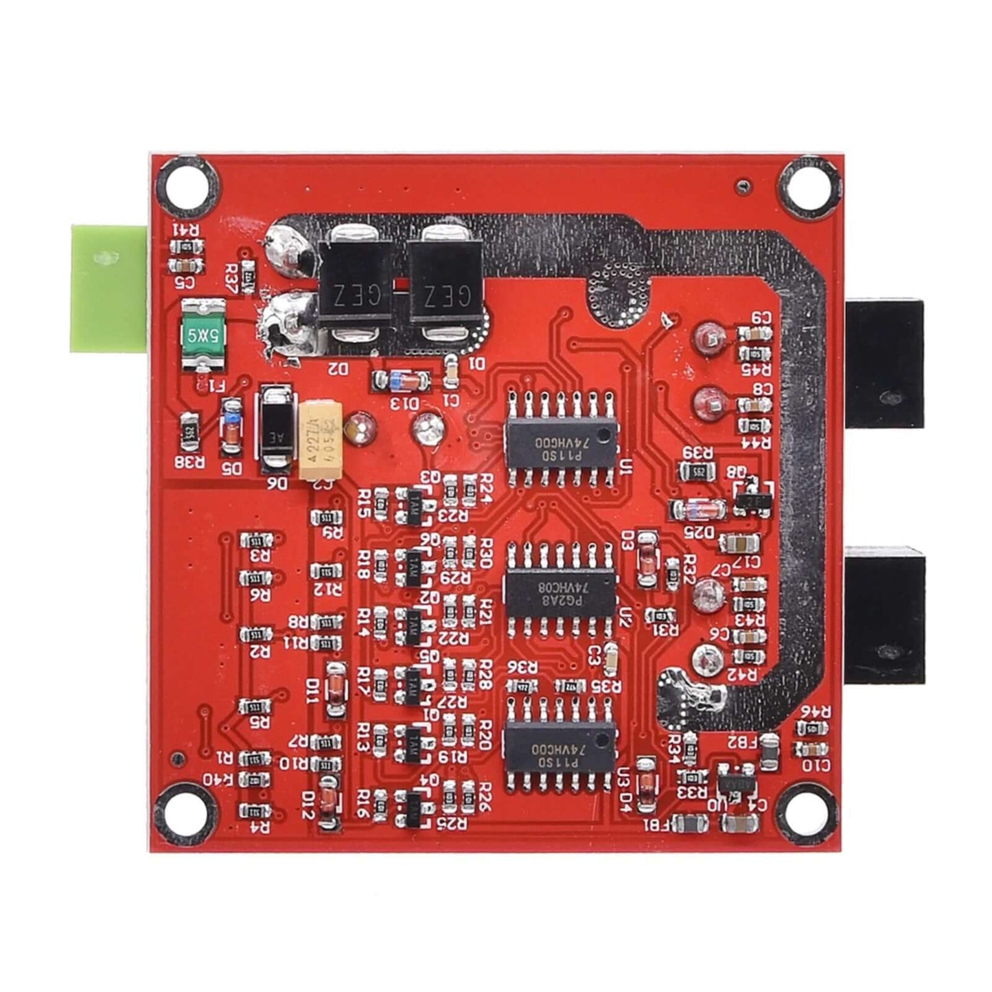
The L298 2 Route Motor Driver Module is a robust dual H-bridge driver designed to control two DC motors simultaneously. With a powerful 7A rated output current per channel (50A peak), and a total power handling of 160W, this module is an excellent choice for demanding robotics, automation, and DIY projects that require precise and high-power motor control. It features a wide input voltage range of 6.5V to 27V and incorporates signal optocoupler isolation for enhanced protection and reliable performance, even in environments with electromagnetic interference. Its stable and industrial-grade design includes electrostatic discharge circuits, ensuring durability and compliance with electromagnetic compatibility (EMC) specifications.
Key Features:
- Dual H-Bridge Design: Capable of driving two independent DC motors simultaneously.
- High Current & Power: Each motor interface offers a rated output current of 7A (50A peak), with a module power rating of 160W.
- Wide Voltage Input: Operates reliably with a power supply voltage from 6.5V to 27V.
- Optocoupler Isolation: Signal input is isolated by optocouplers, providing superior anti-interference capabilities and protecting your control signals from high-power circuits.
- Undervoltage Protection: Built-in protection ensures stable and safe operation.
- PWM Speed Control: The enable terminal (ENA) supports PWM input (0-10KHz frequency) for precise motor speed regulation.
- Industrial Grade Reliability: Designed for stability and reliability, featuring electrostatic discharge circuits and EMC compliance for robust applications.
- Compact Size: Product dimensions are 55 x 55 x 16mm (Length x Width x Height).
Product Parameters:
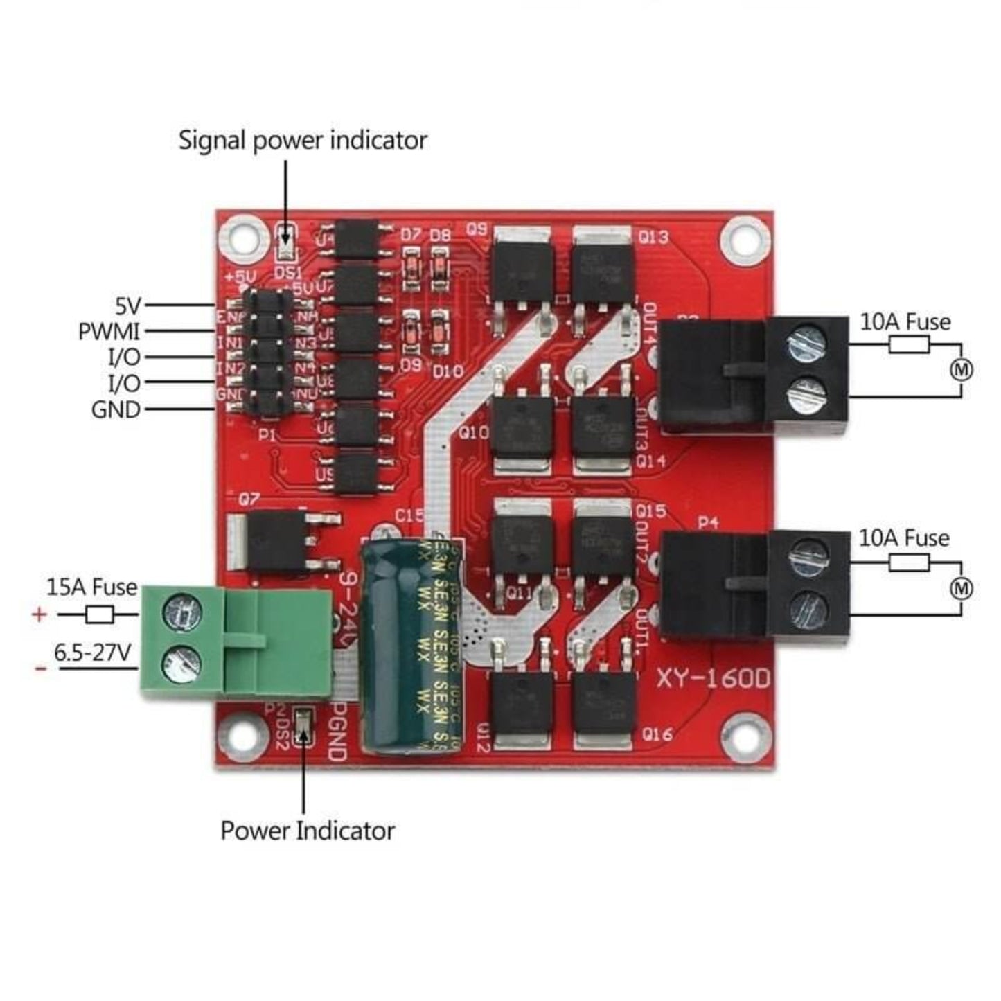
- Motor Interfaces: Dual channels, each with 7A rated output current (50A peak). (Note: Motor interfaces must not be short-circuited; a 10A fuse in series is recommended for protection).
- Power Supply Voltage: 6.5V - 27V (Crucially, the power supply must not be connected in reverse or exceed 27V, as this may burn out the module. It is recommended to use a 15A fuse in series with the power input).
- Working Temperature: -25°C to 80°C.
- PWM Frequency Range: 0 - 10KHz, with a minimum PWM duty cycle of ten beats for reliable operation.
- Control Signal Voltage: 3V - 6.5V (applies to the enable signal and the positive/reverse control signals).
- Installation: Mounting hole diameter is 3mm. Pay attention to prevent short circuits on the back of the circuit board; you can add an insulation pad or copper standoff to raise the board.
Suitable Motor Parameters:
- For 12V Motors: Recommended for motors with a rated power of 40W or below, or a rated current of 7A or below for long-term, full-load operation.
- For 24V Motors: Recommended for motors with a rated power of 115W or below, or a rated current of 7A or less for long-term operation.
Important Precautions:
- Drive Power Connection: The drive power must not be reversed. It is highly recommended to connect a 15A fuse in series with the power connector. The voltage must be strictly between 6.5V and 27V; over-voltage can severely damage the module.
- Motor Interface Protection: Do not short-circuit the motor interface, as this can burn the driver module. A 10A fuse in series with each electrical interface is strongly recommended.
- Forward/Reverse Switching: When switching between forward and reverse directions, a braking period of at least 0.1 seconds is required before reversing. Do not attempt to commute while the motor is still rotating, as this may damage the drive.
- Power Supply Sizing: It is recommended that the rated output current of your power supply be at least twice the rated current of the motor. This ensures the power supply can provide the necessary voltage during motor startup, preventing power loss and motor pauses.
- Motor Generated EMF: When the drive module is powered down, do not directly or indirectly allow the motor to rotate at high speed, as the motor generated electromotive force (EMF) can burn the drive module. If your application requires high-speed motor rotation when the drive module is powered down, it is recommended to connect a relay in series with the driver's motor interface (using the Normally Open (NO) and Common (COM) terminals), with the relay coil sharing power with the driver. This way, when power is down, the relay will disconnect the drive and motor connection.
- Environmental & Handling: Do not expose the drive to moisture. Do not short-circuit any components on the drive board. Avoid touching the pins and pads on the board when powered.
